BIM Project 2a

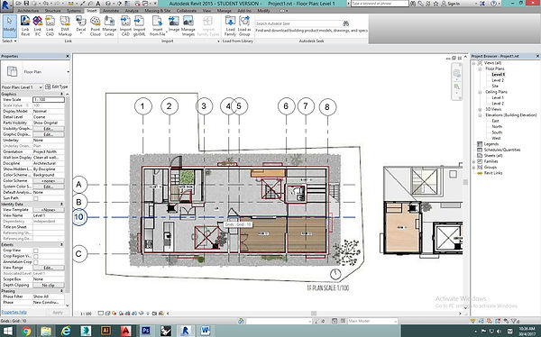
1. Trace the plan layout outline with the autocad to confirm the scale is right.

2. Import the cad drawing into revit. As grid lines were drawn, the heads and tails of the lines can align to one another. Same step repeated for X-axis.

3. Basic walls were drawn following to the grid lines.
Select Architecture > Wall and choose the type of walls from the properties on the left side. Draw the wall as outline where the grid line is in the midpoint of the wall.

4. Create the ground floor.

5. Add the window and doors.


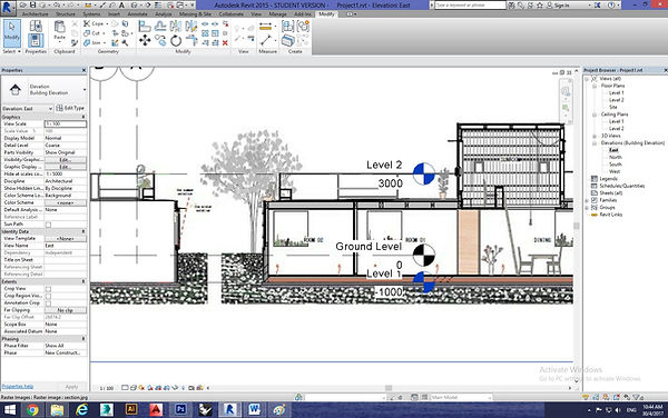
6. Adjust the floor level.


7. Add the wall and floor in first floor and create void with edit boundaries.

8. Draw the roof in floor plans with grid line. To create a gable roof, select Edit Footprint>Choose the roof line>Turn off Undefined slope.

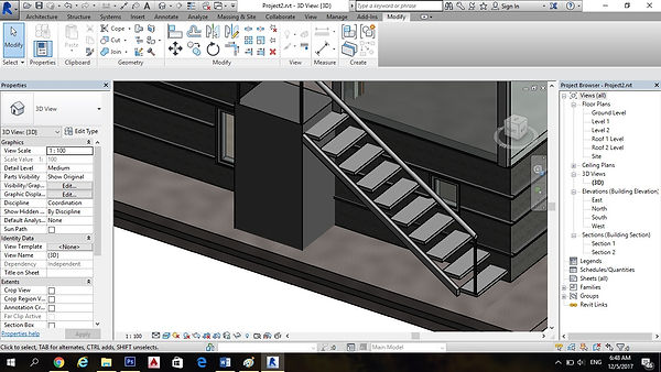
9. Create staircase. Change the setting by turning off the riser to have staircase without riser.
Go to Architecture> Component> Model In-Place> Generic Models> Extrude the Stringer by Set> Click a Place> Draw the outline of the stringer> Extrude

10. Change the railing numbers by setting the distance between two baluster.


11. Clean the background with the image references.

12.Edit type > Duplicate > Rename a new type of wall > Edit > Insert for additional materials in the wall. For this case, the layer above wrap will be masonry while the layer below wrap will be gypsum board. The thickness and material can be changed too.
Insert > Structure > Finish > <By Category > Gypsum > Move Up (Away from Core Boundary)
Create another finish on the exterior
Insert > Structure > Finish > <By Category > Gypsum > Move Down (Away from Core Boundary)

13. Add the wall detail by doing Architecture> Component> Model In-Place> Wall> Extrude


14. Add the railing with adjusting the distance between the each balusters.


15. Open the roof opening.
By Face>Choose the plane>Then Draw the Opening Outline>click and the opening is created.
Create a Furniture family-Bench

16. New > Family >Metric Furniture rft to create a new family for bench.
Shortcut 'RP' to create a reference plane. Select Create > Extrusion and draw an outline for the bench and lock it to prevent accidentally move it. Shortcut 'DI' to measure the distance between reference plane and click label which add the measurement into parameter properties. It enable to change the dimension easier later on.


17. After finished editing, Save as> Family>Load into project.
Create a Furniture family-Ladders


18. New > Family >Furniture rft to create a new family for window. The steps is same as the step of create bench family.

Create a Door family-Sliding door.
19. New > Family >Door rft to create a new family for Door. The steps is same as the step of create bench family.


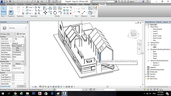
20. Build the structure beam in the upper part cluster blocks.
Architecture>Model In-Place>Structure Framing>Set(chose the place for the beam direction)>
Draw a rectangle for the beam dimension>then confirm modelling


21. Copy and paste for other same beams.

22. Same goes to the columns.

23. Select Architecture > Curtain Grid and select the vertical section to cut a segment. Horizontal segment can be created by choosing 'One segment' and created and the most right side. Select Mullion and choose all grid lines to input mullion into all grid line.


24. Same goes to the another window with mullion.
3D Final Model.


